Autonomous Robotic Foosball
C++ / Nvidia Jetson / TensorRT / Arduino
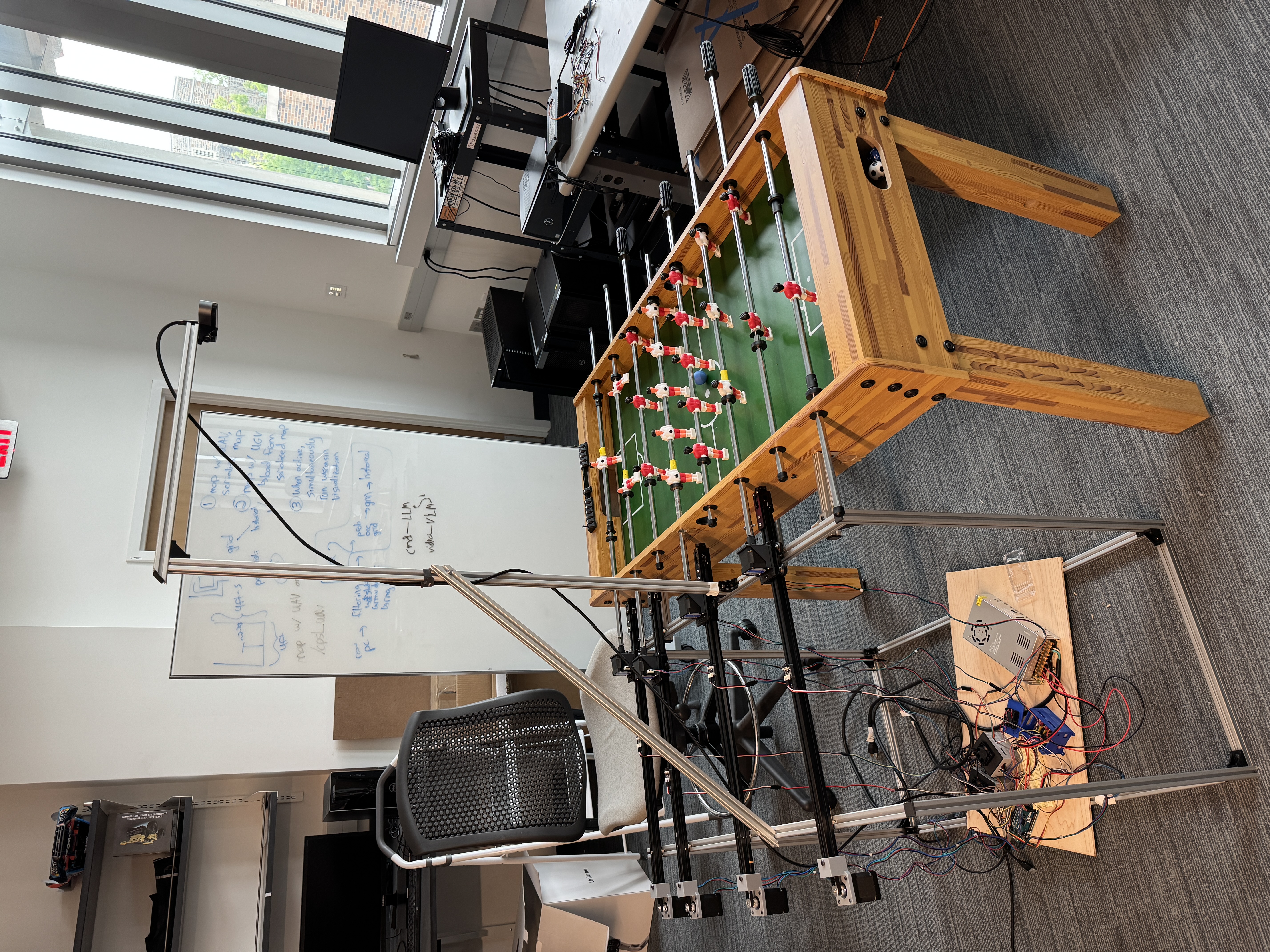
A standard foosball table retrofitted to play one side by itself. An overhead camera tracks the ball, an Nvidia Jetson decides where each rod needs to be, and stepper motors move and kick the rods fast enough to block and score against a human opponent. Built with Aditya Gaur in Duke's Cyber-Physical Systems Lab.
Hardware Implementation

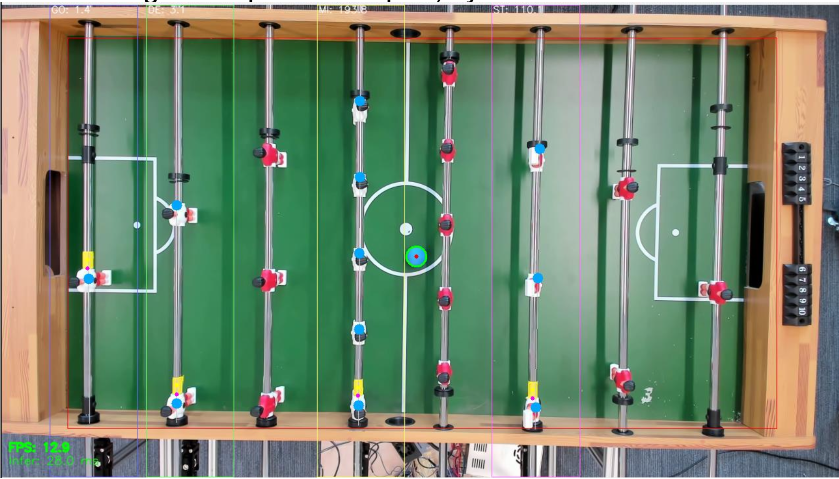
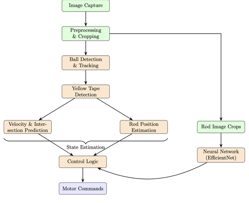
The hardware architecture splits high-level perception and low-level motor actuation. An Nvidia Jetson AGX Orin handles vision processing via a Logitech BRIO stream (720p at 30fps) cropped to the playfield. We convert frames to the HSV color space and apply color range thresholding, followed by morphological open/close filtering, to isolate the blue ball and yellow end-of-rod markers; a centroid calculation on the largest contour provides each object's position. Velocity is computed from the positional delta over a sliding window of recent frames, and the linear trajectory is projected to the intersection coordinate with each rod's x-plane (for multi-player rods, the figure closest to the intercept is selected).
The Jetson transmits MOVE and KICK commands over serial to an Arduino Mega 2560, which drives the eight NEMA-17 steppers (four lateral, four rotational) through AccelStepper acceleration profiles; four limit switches provide the physical zero reference for the lateral homing sequence.
State Estimation & Control
For rotational state estimation, we trained four EfficientNet-B1 regression models, one per rod. The training data came from the rig itself: a collection script homes the lateral rods against their limit switches, then steps the motors through a grid of every rotational and lateral position combination. At each grid point it pauses for vibrations to settle, captures a 1080p frame, and encodes the ground truth directly in the filename (e.g. rot_s14_lat_p40.jpg), so the dataset comes out pre-labeled with no manual annotation. We then augmented the images with randomized lighting, blur, noise, and shift/scale transforms to cover gameplay conditions like motion blur and camera jitter. The models reach a test MAE of 0.82 steps (about 1.5° of rotational error). We quantized them to INT8 with Post-Training Static Quantization (14.5MB down to 7.9MB each) and exported them via ONNX to TensorRT engines; inference for all four rods runs on parallel CUDA streams and finishes in about 14ms, comfortably inside the 30fps frame budget.
To solve stepper drift, the vision system periodically compares the y-position of the yellow tape markers against the position implied by the motor step count. If the error exceeds a pixel threshold, the Jetson sends a RESETPOS command to the Arduino to overwrite its internal step counter, effectively closing the loop without hardware encoders.